|
isce3
0.1.0
|
|
isce3
0.1.0
|
ISCE delegates raster data handling to the Geospatial Data Abstraction Library (GDAL). Hence, it uses all the conventions defined by the GDAL data model to simplify the interface. You will find detailed documentation of all the methods available here: isce3::io::Raster.
ISCE exposes access to GDAL's raster generation capabilities via it's most general constructor interface
This method provides direct access to GDALGetDriverManager()->GetDriverByName()->Create() methods in C++. This provides users with the capability to generate raster imagery in any format with write-support in GDAL. See this table for list of formats supported by GDAL.
Since, ISCE delegates Raster data access to GDAL, (in theory) users should be able to read in any raster format that GDAL supports. A Raster can be easily opened for ReadOnly Access by just passing the filename to the constructor
isce3::io::Raster(std::string& fname)
The same applies to virtual file systems supported by GDAL as well.
The IHDF5 driver is considered a special driver by ISCE and is handled differently.
ISCE uses the same convention as GDAL, i.e coordinates of a raster image are interpreted using the "PixelIsArea" convention.
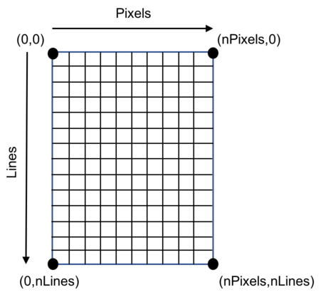
The key features of "PixelIsArea" convention are
For more details on the "PixelIsArea" and "PixelIsPoint" conventions - see the Geotiff spec.
ISCE delegates the association of map coordinates (East, North) to image coordinates (Column, Row) to GDAL and uses the Affine GeoTransform mechanism to represent this mapping. GeoTransform of a raster image refers to collection of six double precision numbers such that
\[ \left[ \begin{array}{c} X_{left} \\ Y_{top} \end{array} \right] = \left[ \begin{array}{c} G_0 \\ G_3 \end{array}\right] + \left[ \begin{array}{cc} G_1 & G_2 \\ G_4 & G_5 \end{array} \right] \cdot \left[ \begin{array}{c} P \\ L \end{array} \right] \]
where P and L refer to integer pixel (column) and line (row) indices of pixel of interest, and \(X_{left}\) and \(Y_{top}\) corresponds to the geographical coordinates of the Top-Left corner.
SRTM uses "pixelIsPoint" convention whereas NED uses "pixelIsArea" convention. See this link for detailed explanation.
Consequently, map coordinates of SRTM data has to be labelled correctly for use with ISCE. This example is to emphasize that when users bring in their own datasets to work with ISCE - they should be annotated correctly with "pixelIsArea" Affine Geotransform information.
Fortunately, GDAL takes care of this adjustment already for SRTM format datasets. You can verify this by running "gdalinfo" on an SRTM tile. Note that the geographic coordinates corresponding to the Top-Left corner has been adjusted by half a pixel to conform to the "pixelIsArea" convention.
> gdalinfo N34W120.hgt
Driver: SRTMHGT/SRTMHGT File Format
Files: N34W120.hgt
Size is 1201, 1201
Coordinate System is:
GEOGCS["WGS 84",
    DATUM["WGS_1984",
        SPHEROID["WGS 84",6378137,298.257223563,
            AUTHORITY["EPSG","7030"]],
        AUTHORITY["EPSG","6326"]],
    PRIMEM["Greenwich",0,
        AUTHORITY["EPSG","8901"]],
    UNIT["degree",0.0174532925199433,
        AUTHORITY["EPSG","9122"]],
    AUTHORITY["EPSG","4326"]]
Origin = (-120.000416666666666,35.000416666666666)
Pixel Size = (0.000833333333333,-0.000833333333333)
Metadata:
  AREA_OR_POINT=Point
Corner Coordinates:
Upper Left  (-120.0004167,  35.0004167) (120d 0' 1.50"W, 35d 0' 1.50"N)
Lower Left  (-120.0004167,  33.9995833) (120d 0' 1.50"W, 33d59'58.50"N)
Upper Right (-118.9995833,  35.0004167) (118d59'58.50"W, 35d 0' 1.50"N)
Lower Right (-118.9995833,  33.9995833) (118d59'58.50"W, 33d59'58.50"N)
Center      (-119.5000000,  34.5000000) (119d30' 0.00"W, 34d30' 0.00"N)
Band 1 Block=1201x1 Type=Int16, ColorInterp=Undefined
  NoData Value=-32768
Unit Type: mWhile GDAL is used to handle rasters within ISCE, ISCE only handles a small subset of projection systems that are supported by GDAL. ISCE exclusively uses EPSG codes for coordinate projection. A CUDA implementation of projection transformations has also been implemented for GPU-based processing. Note that all ISCE supported projections are defined on a WGS84 ellipsoid.
| EPSG code | PROJ.4 string | Common name |
|---|---|---|
| 4326 | +proj=longlat +datum=WGS84 +no_defs | WGS84 Lon/Lat |
| 3031 | +proj=stere +lat_0=-90 +lat_ts=-71 +lon_0=0 +k=1 | Antarctic Polar Stereographic |
| 3413 | +proj=stere +lat_0=90 +lat_ts=70 +lon_0=-45 +k=1 +x_0=0 +y_0=0 +datum=WGS84 +units=m +no_defs | NSIDC Polar Stereographic North |
| 32600+X | +proj=utm +zone=X +datum=WGS84 +units=m +no_defs | Standard UTM zone North |
| 32700+X | +proj=utm +zone=X +south +datum=WGS84 +units=m +no_defs | Standard UTM zone South |
| 6933 | +proj=cea +lon_0=0 +lat_ts=30 +x_0=0 +y_0=0 +datum=WGS84 +units=m +no_defs | EASE 2.0 global grid |
Internally, ISCE needs all DEM heights to be referenced w.r.t WGS84 ellipsoid. However, users can delegate vertical datum transformation for a small subset of geoids to GDAL (gdalwarp with vertical datum). The set of supported geoids that could be useful are
| EPSG code | Name of Geoid | URL |
|---|---|---|
| 5773 | EGM 96 | https://en.wikipedia.org/wiki/EGM96 |
| 3885 | EGM 08 | http://earth-info.nga.mil/GandG/wgs84/gravitymod/egm2008/egm08_wgs84.html |
ISCE uses the isce3::product::RadarGridParameters data structure to represent the radar swath imaging grid limits. Swath imagery uses "Pixel Is Point" convention - i.e, isce3::product::RadarGridParameters::sensingStart and isce3::product::RadarGridParameters::startingRange represent the time-tag and slant range to the center of the Top-Left pixel in the swath which is always arranged in increasing azimuth time order (rows) and increasing slant range order (columns).
 1.8.5.

